
Understanding your Auto Park brake setup and its operation
In the following PDF write-up, we will do our best to explain the whole AutoPark brake setup and its operation is not something you can easily understand at a glance. They designed this floating concept to keep the shoes sort of self centering in the drum. At the same time, the geometry is such that the left and right shoes get equal pressure when the brake is applied. Rather clever of them but the basic design has been around a LONG time.
Click on image to enlarge

Brief explanation:
- Cable pulls to the left on Lever when brake is applied
- Transfer bar (dunno what it is properly called) moves to the left and transfers movement from point B to point A pushing out the left hand shoe
- Can’t be seen in picture above, but the bottom of the lever is fastened at pivot to right hand brake shoe
- So when lever is pulled to left by cable, shoes will spread. Space between them under the retainer (at the bottom) will get wider. Funny shaped washer keeps the shoe ends in place.
- At the top of the picture, the shoe ends will be bearing on the adjuster, and will pivot on those ends when the brake is applied.
- Spring across adjuster and two springs at the bottom are what retract the shoes when brake is released. They also keep some tension on the cable when the brake is released.
- Since this whole mechanism is not RIGIDLY fastened to the backing plate, it sort of “floats” and is self centering – – So equal pressure is applied to both the left hand and the right hand shoes.
Click on image to enlarge
Download the whole AutoPark brake setup and its operation PDF here
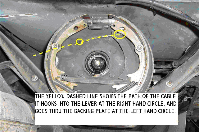
Questions and comments are always welcome, oldusedbear


