
Adjusting brake shoes for AutoPark parking brake system
This document is a compilation of several separate write-ups. What we’re trying to do here is consolidate the necessary information needed for you to make an adequate shoe adjustment (or shoe replacement) for your AutoPark parking brake assembly.
On all versions of AutoPark, there is a drum brake on the driveline – – right behind the tranny. Adjusting it is much like doing the brakes on an older passenger car. If you have never done this job before, either find a friend who has done it and will help you, or let me know and we will have to send you some additional information.
This brake utilizes a “star wheel” type adjuster as you would find on a car, but instead of accessing it thru a port on the backing plate, on your RV the port is in the brake drum itself. This means you need to have the drum properly oriented to reach the adjuster thru the port.
A lot of the AutoPark literature shows the adjuster to be at the 6 o’clock position but EVERYONE I’ve ever talked to says it is at 12 o’clock.
So, you need to securely chock the wheels, and jack up one rear wheel off the ground – – that way you can turn the driveshaft by hand. On any coach that has the separate pump and reservoir (94/95 and later), you will need the ignition ON, but engine NOT RUNNING – – Shift lever in NEUTRAL. On the older versions that run AutoPark off of the power steering, you will need the foot pedal to be in the released position, AND either have the engine running with the gear shift in neutral, OR somehow cage the actuator so the brake is NOT APPLIED. Newer versions will need the yellow knob pushed IN, as well as having the shift lever in NEUTRAL.
Get under the rig and orient that port on the brake drum to 12 o’clock. Open the port and get it over the adjuster; Then, click the adjuster until you get just the slightest drag. If your version has a foot pedal in addition to the PARK position on the gear selector, go try your foot pedal for the park brake. If that works OK, try the AutoPark on a slope to make sure it will hold the coach satisfactorily on a hill. If you do not have a foot pedal for the park brake, just checking the AutoPark will be the only thing necessary. If the AutoPark is working well, but the foot pedal is not, you may need to adjust the cable on the foot pedal.
The following shows some diagrams and supporting information on what the brake assembly looks like:
Click on image to enlarge

The above is a modified drawing. It was originally lifted from the manual, but then inverted. The original version of this in the manual shows the star wheel adjuster at the bottom of the assembly, when in fact all of them we know about are at the top.
Here is the legend that goes with the modified drawing:
IMPORTANT NOTE: This legend goes with a modified drawing of the parking brake drum and associated parts. The original drawing lifted from the manual, mistakenly shows the parts inverted – – with the star wheel adjuster at the BOTTOM of the backing plate instead of at the TOP where it is actually located. This new legend and the modified drawing reflect what you should see if you take apart the parking brake assembly. Also please note than when you install the #11 Adjuster, that the star wheel should be on the left side of the adjuster instead of the right side – – It will fit in either way, but the left side is more traditional. The modified drawing shows it on the right side, but I could not easily modify that portion of the drawing.
| 1. NUT, ANCHOR PIN | 11. ADJUSTER, BRAKE SHOE |
| 2. PLATE, BACKING | 12. SPRING, BRAKE SHOE ADJ. |
| 3. PIN, ANCHOR | 13. CUP, HOLDER PIN SPRING |
| 4. PLATE, GUIDE | 14. SPRING, HOLDER PIN |
| 5. WASHER, WAVE | 15. WASHER, HOLD |
| 6. STRUT, SHOE LEVER | 16. LEVER, PARKING BRAKE |
| 7. SPRING, SHOE LEVER STRUT | 17. BOLT |
| 8. RING, SHOE LEVER | 18. WASHER, SPRING LOCK |
| 9. SHOE, PARKING BRAKE | 19. PIN, SHOE HOLDER |
| 10. SPRING, PULL |
Click on image to enlarge
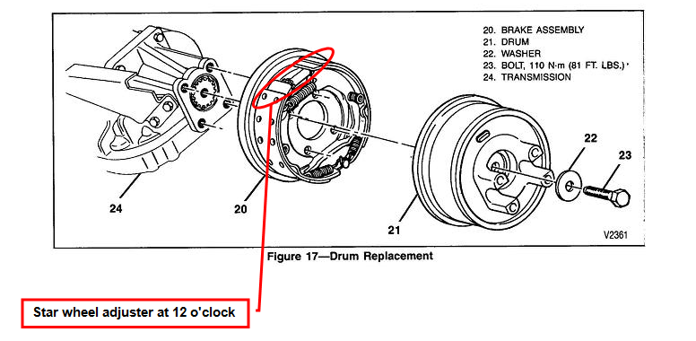
The above drawing shows the drum in its proper orientation with the adjuster at the top of the backing plate – – more or less in line with the little port you can see on the drum. It also shows the bolt (#23) that holds the drum on. A common mistake is to assume that the four bolts that hold the backing plate to the back of the tranny, also hold the drum in place. This is not the case – – The single bolt is what holds the drum on.
Click on image to enlarge
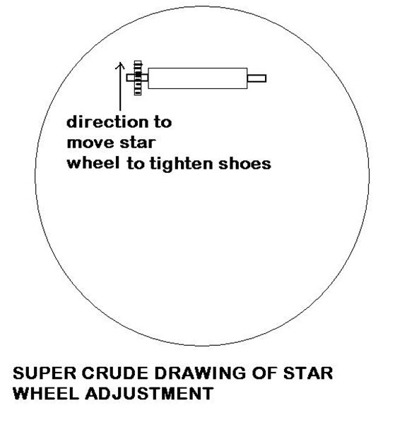
The above crude drawing is an aid in locating and adjusting the star wheel. I’m sure you will find it at the 12 oclock position of the backing plate. Again, this means you will have to rotate the drum such that the star wheel port which is in the rotating drum – – NOT the backing plate, is located over the star wheel. The port is NOT in the backing plate as it was in the old family car.
Side note :If you find that you DO need to replace the shoes of your AutoPark parking brake, and you’re having trouble finding part numbers, sources etc., don’t forget there are still places that can re-rivet or bond new lining on your old shoes. You simply provide them with your old shoes and they refurbish them.
We refer to this AutoPark brake assembly as a “short throw system.”
What do we mean by that? The following hopefully explains:
All the GM/Chev/Workhorse J71 AutoPark systems, as well as the earlier units that run off of the power steering, utilize what could be described as a “Short Throw” system. The best way to describe this might be to compare it to a regular wheel drum brake on the family car.
Typically, the brake pedal on a car could be 4 or 5 inches above the floorboard. If the brakes were in need of repair, the pedal could conceivably go almost to the floor before any braking occurred. In this case, you could say that the total throw of the pedal system was 4 or 5 inches. Once repaired and/or adjusted, this travel distance might be only 1.5 or 2 inches until the pedal became firm and the brake applied.
In the AutoPark configuration, a properly adjusted system has a total throw at the actuator, of about 1.25 inches. In other words, the actuator which applies or releases the parking brake, only moves about 1.25 inches between the “brake applied” condition, and the “brake released” condition.
If the actuator is moving much more than a maximum of 1.45 inches, then the brake probably is not holding well on an incline and the actuator is said to be in “over travel.” If the actuator is moving less than 1.25 inches, it is quite possible that the brake shoes are dragging some – – even in the released condition. It should be noted that the 1.25 to 1.45 inch travel range is not absolutely sacred – – it could be slightly more or slightly less, but large deviations will probably indicate a system which is either too tight, or too loose.
Additionally, there is a lever arm in series with the cable system for AutoPark, and due to the configuration of this lever arm, when the actuator moves 1.25 inches, the cable going to the brake drum may only move about an inch. So we can say that even with good, properly adjusted shoes, the brake cable to the drum should be moving only about 1 inch between a firmly set brake position, to a totally released and non dragging position.
Because of the above stated considerations, it is absolutely essential that the slack/tension adjustment in the cable system between the actuator and the shoes, be just about perfect. Any extra slack and the brake will not hold firmly, and too much tension will have the shoes dragging. While such a system can tolerate almost no wear or cable stretching without need for adjustment, it must be remembered that this is a static brake – – not a dynamic brake. It is NOT supposed to be used to stop a coach that is already rolling – – It is only used to keep the vehicle from rolling in the first place. As such, the brake linings should never wear appreciably unless something has malfunctioned.
So how does all the above affect the requirements and procedures for setting up a properly functioning AutoPark system?
To start with, we need shoes which are in good shape to be adjusted such that with zero tension on the brake cable going to the drum, the shoes are just barely touching the drum – – sort of a “no clearance but no drag” condition.
There is a cable going from the brake drum to the lever relay – – as depicted in the following illustration of the lever arm assembly:
Click on image to enlarge
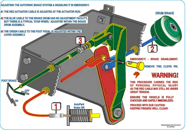
In this case, we are talking about the #2 cable. The cable itself, has no adjustment capability, but slack in this portion of the system must be removed by adjusting the brake shoes themselves – – via the star wheel.
The RED cable however, can be adjusted at #1 where it attaches to the actuator shaft. There is an adjustment nut which makes this possible.
At #3, the foot pedal (if your coach has one), can be adjusted by loosening the lock nut, pulling the clevis pin, and rotating the clevis to either tighten or loosen the effect of the foot pedal – – Then, replace the clevis pin and tighten the lock nut. This cable and the foot pedal are isolated from the actuator by the design of the lever system. This means that adjustment of the foot pedal does NOT affect the adjustment of the actuator and brake shoes. However, the opposite is not true – – If you snug up the shoes, it will be felt at the pedal. If you add, or remove slack at the actuator, it will have little effect at the brake pedal.
Sooo – – To put a bow on this entire package, we need an adequate understanding of all the above principles and details. With this knowledge, we can carry out proper adjustment of the shoes and the related lever and cable systems.
The proper sequence of service to this system would be:
1. Determine that the drum, shoes, lever relay and cables are all in good condition.
2. Adjust the shoes as described above.
3. Adjust the cables as described above.
4. Test the system to be sure that the shoes are NOT dragging in the “brake released” condition, and that the AutoPark (PARK position on the gear shift lever) will adequately hold the coach on an incline.
Meeting all these requirements is really a sort of balancing act, and may be somewhat difficult to understand and accomplish.
Download PDF Adjusting brake shoes for AutoPark parking brake
Questions and comments are always welcome, oldusedbear


