Salvaging Solenoid Valves
This is something that has been found to work on several occasions – – a process for cleaning up a sticky solenoid valve.
Remove the coil from the core assembly. Then remove the core from the aluminum (gold colored) block.
Soak the core in mineral spirits for several hours. Then, blow it out with compressed air.
Shake the valve vigorously in an end to end motion. The idea is to free up the rod (#7 in the illustration) so it slides back and forth easily. If it is really free to move, you can hear it click when you tip the core back and forth in a teeter totter fashion. If you can hear it click only with vigorous shaking, then it is still sticky. Soak it some more, and shake it some more.
When it is truly clean, it will slide freely with just the gentle teeter totter motion. It is moving by its own weight – – no springs in there. You will hear the click each time you tip it in the opposite direction.
This procedure works in most all of the cases where the valve is just sticky. Stronger solvents such as Chemtool B12 may work better than mineral spirits.
|
Click on image to enlarge
|
|
|
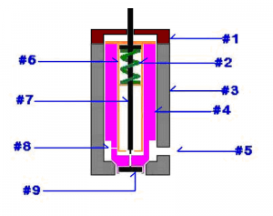
SOLENOID VALVE — CONCEPTUAL AND NOT TO SCALE. DOES NOT INCLUDE THE COIL
|
|
 |
|
|
LEGEND FOR SOLENOID VALVE ILLUSTRATION
|
|
- This depicts an end cap for the valve assembly when actually there is something quite different in this position. The mechanism above this point includes the coil, and a sealed tube which contains the slug that is forced downward when current is applied to the coil.
- A rather poor depiction of a small coil spring (green in color). The spring keeps #7, the needle valve rod retracted with NO current to the coil.
- The outer valve casing. VERY hard steel.
- The inner valve casing. Also hardened steel. When current is applied to the coil, the #7 rod is forced down into contact with the #4 inner valve casing. This seals the small port directly below the #7 needle valve rod, AND forces the entire #4 inner casing downward – – effecting a seal between the inner casing #4 and the outer casing #3.
- This is the inlet port to the entire valve assembly. When the valve is open (no current applied), the ATF flows in thru #5 and out thru the bottom of the outer valve casing #3.
- This is a brass tube that holds the #2 spring, and #7 rod in place.
- This is the needle valve rod. When current is applied to the coil, this valve is forced downward, compressing the spring and closing both the small port at the bottom of the needle rod AND the larger valve formed by the #4 inner casing and the #3 outer casing.
- This is a VERY tiny hole that is apparently a pressure equalizing vent.
- This is a little button valve. It is captured in position but can “float” in the up and down direction. It pretty obviously can prevent flow backwards up into the valve bodies, but just what that accomplishes, I have yet to figure out. It opens directly into the exit line going to the reservoir, which is never under pressure other than atmospheric. Ideas cheerfully accepted. It sure looks to me like the downward pressure on the #4 inner valve is greatly increased by the 1600 psi pressure of the pump. I question whether the solenoid by itself could effect a tight seal without help from the pump pressure. The #9 button is still a bit of a mystery
|
|
Questions and comments are always welcome, oldusedbear
Download PDF how to Salvage Solenoid Valves here