
THE IMPROVED 3 LIGHT GENIE LAMP ACCESSORY
This package consists of text, circuits and diagrams that describe an auxiliary dashboard warning light system. It operates independently of, and in addition to the regular AutoPark dash light. In this document, we are going to try to consolidate a whole bunch of stuff about the Genie Lamp instead of having it on four or five separate write-ups.
With the addition of this three light module, it is possible to monitor normal operation of the AutoPark system, and also detect potential problems as they develop. Even more importantly, it provides real attention-getting evidence of an imminent parking brake lockup.
This is a device that most forum members should be able to assemble and install themselves – – with parts costing less than 20 dollars.
NOTE: This modification pertains only to the Version II and Version III AutoPark systems that run off of a dedicated pump and reservoir. It DOES NOT apply to the earlier version that runs off the power steering pump.
—————————————————————————————————————————
To understand the whole concept behind the Genie Lamps, we need to first examine the AutoPark idiot lamp setup that comes with the GM AutoPark equipped chassis. The explanation is as follows:
Most so called “idiot lights” on a vehicle’s dashboard have earned this derogatory label because they merely indicate the presence of some particular quantity – – There is some oil pressure, but we don’t know how much. The battery is receiving some charge, but we don’t know how much.
One could argue that these lights are providing as much information as some drivers can understand or put to use. Once in a while, a simple on or off indicator lamp can indeed tell you most of what you need to know – – Door ajar might be a good example. Pretty clear cut – – one of your doors is not completely latched.
Then for some of us with motorhomes, there is the AutoPark Light. In my view, it truly deserves nomination as one of the quintessential idiot lights of all times. Allow us to explain our harsh judgment:
On Chevy/GM, or WorkHorse chassis built (approx.) between mid 1994, and some time in 2007, almost every unit (over 16000 lbs. GVWR) is equipped with an AutoPark indicator lamp somewhere in the instrument cluster. While there are some variations in the wiring schema for units built during this period, all of the AutoPark lights are fed by two different signals:
1. There is a pressure switch attached directly to the back of the actuator. This switch will turn the AutoPark Light ON at pressures lower than 500 psi. So if the AutoPark system is seeing pressures anywhere from 500 psi down to zero psi, this switch will illuminate the AutoPark Light. Interestingly tho, this switch has no influence upon anything else in the system. Whether it works or not, it basically has no effect on the drivability of the coach. The exception to this is if the switch develops a short to ground – – in which case it will blow the AutoPark fuse and you WILL get a brake lockup. The shorts are quite rare though – – fortunately.
2. Then we have the infamous Rotten Green Switch – – aka pump motor switch. When this switch senses pressures below 1200 psi, it turns on the pump AND the AutoPark Light on the dash. Thus emerges the rub – – The Light switch turns the AutoPark Light ON when the system pressure gets below 500 psi, and the RGS turns the AutoPark Light AND the pump ON when the system pressure gets below 1200 psi. So how do YOU know which switch turned on the AutoPark Light??? Answer: You probably DO NOT know!
Now – – Let’s confuse the issue a bit more. Typical failure of the Light Switch will turn on the AutoPark Light – – and it will stay ON regardless of what the RGS is or is not doing. But typical failure of the RGS (Rotten Green Switch) will also turn on the AutoPark Light, regardless of what the Light Switch is doing.
Soooo – – The AutoPark Light goes on as you are travelling down the road. Why?
1. You could have an internal pressure leak in the AutoPark system. The RGS sees that there is not enough pressure and turns the pump AND the AutoPark light ON. If the leak is not too big, the pump can stay ahead of it and keep the brake from locking up – – but your pump is running overtime to make this happen.
2. The RGS has gone bad and has turned on the pump AND the AutoPark light. Pressure will go thru the roof and soon rupture the RGS or some other component. Then, the brake will automatically apply.
3. The Light Switch has failed, and turned on the AutoPark Light. Nothing in particular will happen as a result of this but it DOES mask whether or not the RGS is turning the AutoPark Light and the pump ON or OFF. You do not really have an emergency, but the AutoPark Light will not share this secret.
So what are we to conclude from all this? Basically, we have a binary reporting system that gives us only a small amount of the available information. If the AutoPark Light is ON, you may have a BIG problem, a modest problem, or almost no problem at all. If the AutoPark Light is OFF, you may have a BIG problem, or no problem at all.
Now is THAT a great idiot light or WHAT?
What to do?
We very highly recommend that anyone who has a coach with the J71 (the most common) version of AutoPark, build and install our Genie Lamp system. This is a simple and cheap (less than 20 bucks in parts) device that consists of three small indicator lamps. Most any DIY RV’er can build and install it with no difficulty.
Since the Version II and the Version III each have slightly different wiring diagrams, we will show the modified block diagram for both. These diagrams have the Genie Lamps inserted and will help you with your modification. Later in this document, we will give more specific information as to where the physical connections can be made.
Version II AutoParks are found on (approx.) mid 1994 to mid 1998 chassis. Version III AutoParks are found on (approx.) mid 1998 thru 2007 chassis.
Here is the block diagram for the Version II chassis. The Genie Lamps are added to show their location as regards the circuit.
Click on image to enlarge
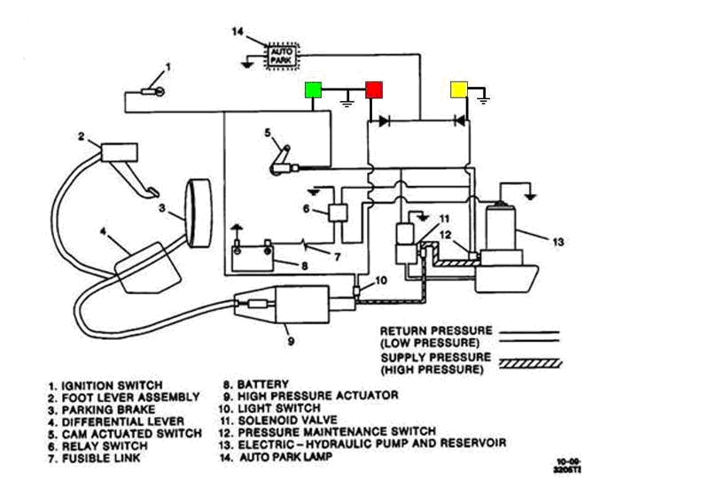
The above diagram shows the insertion of the three Genie Lamps. This is the circuit you should use for coaches built between about mid 94 and mid 98. These chassis have both an AutoPark function (PARK position on the gear shift lever) as well as a manual foot pedal that can apply the parking brake. The foot pedal will be located to the left of the steering column.
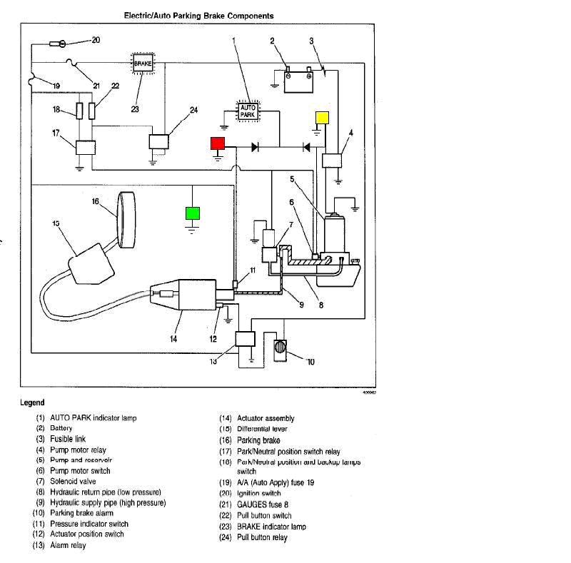
On the next is the block diagram for the Version III AutoPark system. Again, the Genie Lamps are inserted into the circuit, and we will give more specific information on where the actual connections are to be made later in this document.
Click on image to enlarge
In the next illustration, we will show you the different possible combinations of Genie Lamp illumination. All of them are important as they tell you what is happening in your AutoPark system as you are going down the road. Learning to read these lamps will be as important as watching your fuel gauge, temperature and oil pressure.
Click on image to enlarge
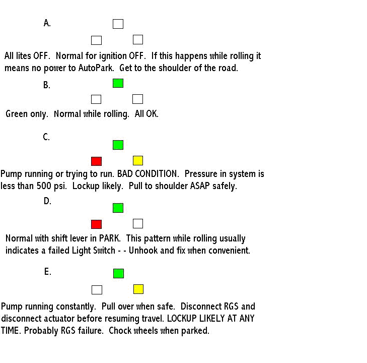
The previous illustration shows the different combinations your Genie Lamps may display. Some are normal, some are more of a problem, and some are serious enough to require immediate attention. The following is a legend that expands upon the different lamp conditions, and explains in greater depth just what each condition means.
The following legend is meant to supplement the basic five part Genie Lamp Guide
Condition A – – All lights are OFF. This is acceptable ONLY if the ignition is OFF. Under any other condition, parked or rolling, it means you have lost voltage to the AutoPark control circuit. If you are rolling, your parking brake has ALREADY APPLIED. Be advised that at road speeds, your engine can overwhelm the parking brake, so you CAN make it to the road shoulder. Do NOT try to get to the next exit or go any further. Your brake is ON and you are cooking your brake drum and shoes. If your emergency stopping place is suitable, you could try troubleshooting and repair of the malfunction. The other options are to disconnect the RGS and the parking brake cable, or call a tow truck.
Condition B – – Green lite ONLY is ON. This is the normal state while rolling. Exactly what you want as you go down the road.
Condition C – – Your AutoPark pump is running or trying to run. The system senses that the pressure is below 500 psi. Normal going down the road pressures should be around 1600 psi – -THIS IS A BAD CONDITION. If lockup has not already occurred, it is likely to happen at any moment. DO NOT TRY TO LIMP TO DESTINATION. Pull off road and pull the connector off of the RGS (the pump motor switch – – can be either green or brown). Also disconnect the actuator cable or otherwise disconnect the parking brake. You will have to chock your wheels until repairs can be made.
Condition D – – This is the normal condition with ignition ON, and shift lever in PARK. This condition WHILE ROLLING, usually indicates a failed LIGHT SWITCH. You can simply remove the connector to the Light Switch and replace the switch later when convenient. Not an emergency situation UNLESS THE LIGHT SWITCH IS RUPTURED AND LEAKING OIL. The possibility of this happening is fairly low, but still a good reason to carry a spare Light Switch..
Condition E. – – Your AutoPark pump is running constantly, or at least trying to run constantly – It could be stalling. This is the usual sign of first stage RGS failure. As long as the RED lite has not gone ON, you still have system pressure holding the parking brake in a RELEASED condition. Not an instantaneous emergency, but you could have a lockup at any time. Get to a safe location right away. Disconnect the plug on the RGS and disconnect the cable to the parking brake drum. DO NOT TRY TO LIMP TO DESTINATION. You run a high risk of burning up your AutoPark pump motor.
The final portion of this document is dedicated to specific instructions on hooking up the Genie Lamps to the proper connections. Failure to do this will probably result in having some of the lamps ON, when they should be OFF – – or vice versa. There are a lot of choices to be made in this installation process, and we don’t pretend to cover every possibility that may arise. We suggest that you give it your best shot, and then if something doesn’t work properly, get back in touch with us and we’ll sort it out a step at a time.
MAKING THE CONNECTIONS
The earlier versions of AutoPark (from 94 up to about mid 1001) have the pump and most of the other goodies under the coach, but the later versions do not. So you need to access the wires going to the Light Switch and the RGS under the coach for your Genie Lamps IF you have one of these versions..
From about mid 2001 though, the Light Switch is still under the coach but the pump and reservoir including the RGS/RBS, have been moved up front under the utility hood.
So if you have the 94 to 98 version, connections for all three colors of Genie Lamps will be made under the coach.
If you have 98 to 2001 version, connections will be made under the coach for the Light Switch (red lite), under the dash for the yellow push pull switch (green lite), and under the coach for the RGS (yellow lite).
If you have the 2001 and later version, connections will be made under the coach for the Light Switch (red) only. The green lamp will be connected under the dash on the yellow push pull switch. The yellow lite will be hooked to the pump motor switch (RGS or RBS if it is brown instead of green) up front under the utility hood.
With the ignition ON (don’t start engine) and shift lever in REVERSE, – – both of those pressure switch (the grey Lite Switch and the green or brown pump motor switch [RGS RBS] ) connectors will have one of their two terminals with 12 volts present. However, you want the terminal that is switched – – not the one that is hot all the time.
So – – On the RGS female connector, the terminal you want can be found by turning on the ignition, (don’t start engine), pull the shift lever OUT OF PARK TO REVERSE, and checking for voltage between ground, and at both of the two terminals. One will show 12 volts, the other will not. You want to tap into the one which does NOT show 12 volts – – and send the info on that wire to your yellow Genie Lite. If you pick the wrong terminal, the yellow lite will be ON all the time. You want it to go On only when the pump is running.
On the Light Switch female connector, you do a similar test – – Ignition ON, don’t start engine. LEAVE SHIFT LEVER IN PARK FOR THIS TEST.
Pull the female connector off the Light Switch and check for voltage between the terminals and ground – – One terminal should be hot, and one cold – – You want to tap into the cold one. If you tap into the wrong wire on THIS connector, the red Genie Light will be ON all of the time – – You want it ON only when you are in PARK.
HERE IS A CHANGE FROM OUR EARLIER INSTRUCTIONS:
We have found a much better system for “tapping into” an existing wire. Instead of using the folding “matchbook” type of connectors which you squeeze on with a pair of pliers, we now (enthusiastically) recommend the newer “push-in” type of connector. These are available at OUR local Ace Hardware so assume you should probably find them there also. Here is a link to Amazon who has better pricing than most.
As for the best place to tap the system for the green Genie Lamp on the 98 and later coaches, I think the best spot would be the incoming wire to the yellow pull switch on the dashboard. That should always have 12 volts coming to it if the ignition is ON. What we’re trying to do here is to monitor the supply of 12 volts for the entire AutoPark control system. If you lose that 12 volts, you’re gonna get a parking brake lockup for sure! This normally happens only if the fuse blows, or if your alternator conks out and the battery goes dead. This is crucial information to have.
Of the two wires going to the yellow knob switch, one will ALWAYS have 12 volts on it if the ignition is ON. The other connection on the switch will show voltage depending on how the switch is set. You have to use the one that is hot whenever the ignition is ON.
I know all of this can be confusing but you have to do it correctly for the Genie system to work properly. You can be comforted by knowing that getting the wrong wire on either of the pressure switches OR the yellow push pull switch, will NOT ruin anything. It just goofs up whether or not the lights work as they should.
Supplemental info on the necessary supplies to build the Genie Lamp:
The parts can be purchased from your local Radio Shack (or similar) store. For trial purposes, I bought their 276-0270 12 volt LED. It is REALLY bright and costs only 2 bucks. They have some nice little black plastic enclosures also. The necessary amount of 3 conductor, 18 gauge wire and some crimp connectors, completes the parts list for the module – – but I would add a supply of wire ties for installation.
To polish off this presentation, we’d like to show you what we feel is the nicest Genie Lamp installation we have seen. The wood paneling is a DIY addition that was placed over the OEM plastic dashboard. The lamps were then installed – – classy job! Scroll down to the final page to see and appreciate.
This is a pretty long and complicated document. If you have questions or comments, or if you get stuck on this project and need help, contact us.
Download complete Genie Lamp PDF instructions here
Comments and questions are always welcome, oldusedbear


